
Engineering

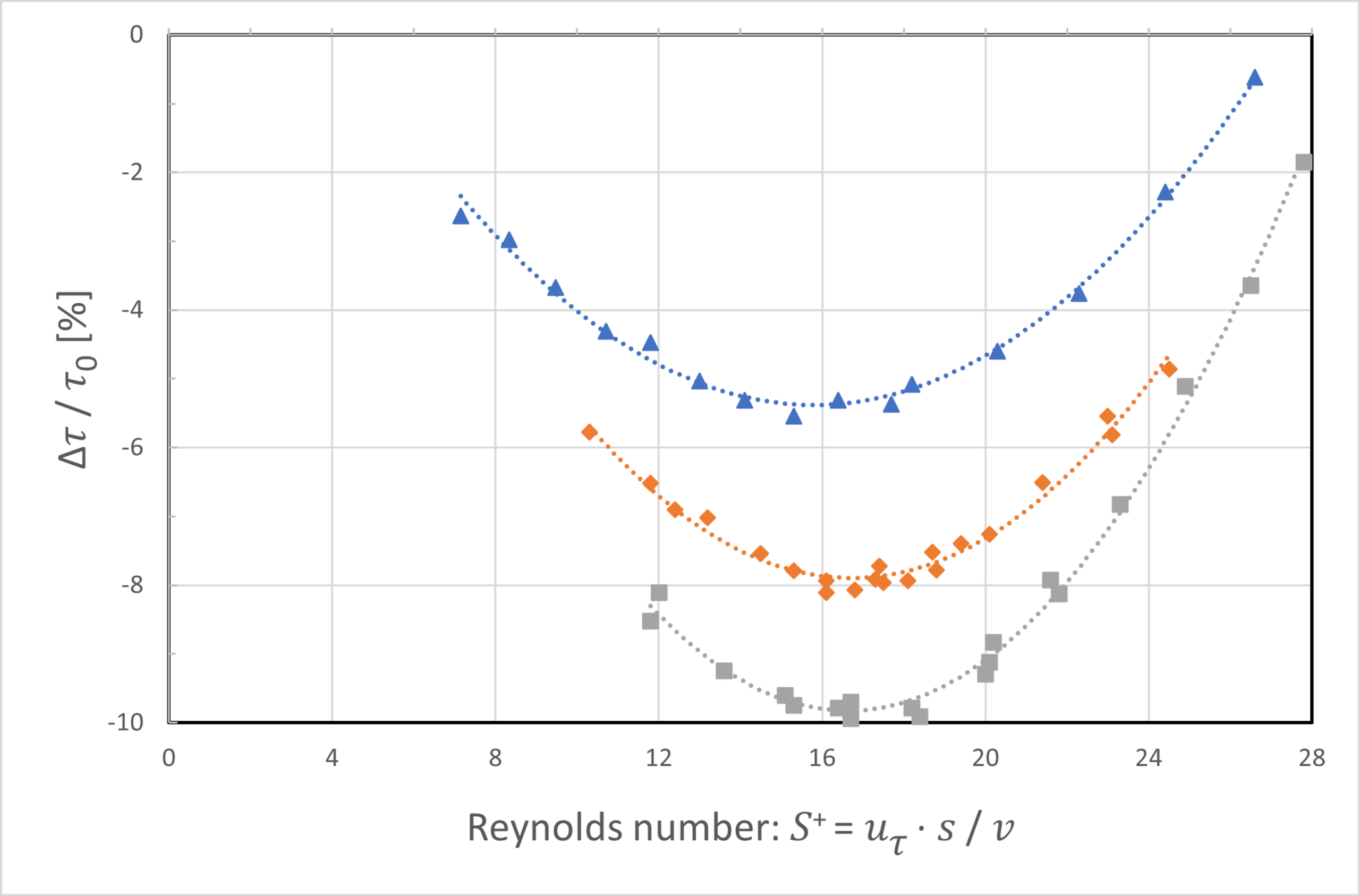
Riblet surfaces are an effective features to passively lower the surface friction and reduce fluid-dynamic drag. By interacting with the turbulent boundary layer, a remarkable reduction of up to 10% can theoretically be achieved. However, in practical applications up to 8% of reduced drag are realistic for the optimal and simple case of a flow over a flat plate. To maximize efficiency gains, Riblets must be adapted to the local flow conditions and therefore vary in size and orientation depending on the specific location on an object’s surface. The ideal Riblet size is basically a function of the fluid’s properties, mainly viscosity, and the flow conditions, mainly velocity. In this sense, the tip to tip spacing of Riblet structures largely alters between 10 and 1000 micrometers.
Valid and accurate data for the design of Riblet surface structures is created by the deployment of Computational Fluid Dynamic (CFD) simulations. Simulation methods further enable the creation of digital twins, which provide reliable information about performance and operational behavior of a system. The feasible Riblet layout for an object depends on the specific manufacturing technique.

The successful implementation of a Riblet solution requires a comprehensive and interdisciplinary approach that considers the entire system. According to the specific operational conditions, different manufacturing methods with distinct characteristics are necessary. By applying best suited Riblets considering producibility and material lifespan, optimal technical performance can be achieved.
The virtual Riblet Design must be translated to the manufacturing methods’ technical language. For instance, laser manufacturing requires different inputs compared to foil application.
However, significant performance gains can be achieved by applying Riblets only to areas with a high impact. This approach also enhances the cost-effectiveness of the overall application.
All these requirements must be considered and can be validated through proof-of-concept testing. If customer requirements are fulfilled, Riblets can be delivered, and the quality of Riblets can be ensured through maintenance agreements.

Crucial components for the research and the development of Riblet technology, as well as for the design of specific Riblet applications, are experiments. The data which is collected on explicit Riblet testing facilities largely contributes to a comprehensive understanding of Riblet effects in distinct operating conditions. Furthermore, the obtained information is integrated in simulation models and digital twins to improve the accuracy of approximations.
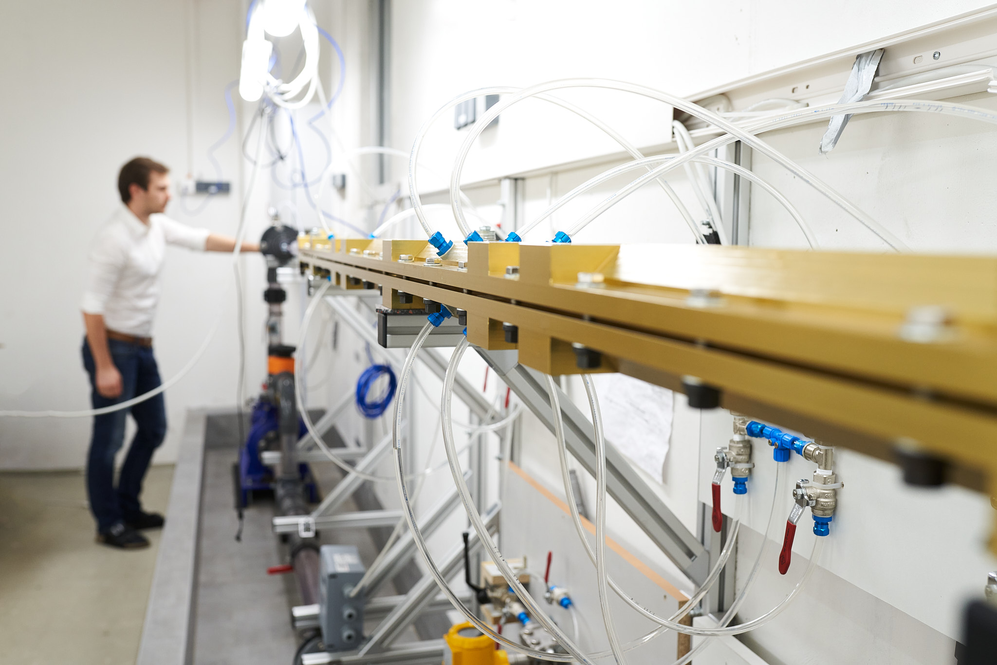
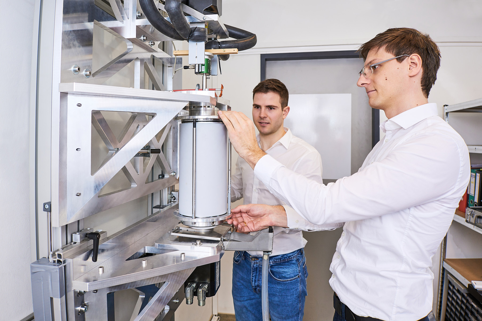
One test rig is a “Taylor-Couette” setup, which describes two axial aligned cylinders, whose gap is filled with a fluid. Riblet structures are applied to their inner surfaces and by comparing measurements of the torque of the rotating cylinder, drag reductions become apparent. Another test facility is the “Pipe Flow Test Rig” at which a pressure gradient in a pipe system with Riblet surfaces is measured. Additionally, a “Small-Scale Wind Tunnel” is available for testing air foils.
On the one hand, these testing facilities help to predict a prospective operational performance. On the other hand, they are valuable elements of ongoing quality control and help to ensure the technologies performance over the product life cycle.